
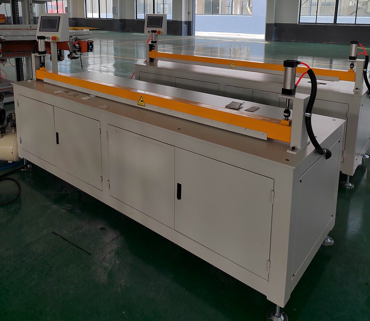
Distribution Fin Cutting Machine for Plate Fin Heat Exchanger
The distribution fins are ones of the important brazed components of the aluminum plate-fin heat exchanger. The cutting of the distribution fins is a key process in the manufacturing of the aluminum plate-fin heat exchanger. The production quality of the distribution fins directly affects the assembly quality and brazing quality of the core body. Therefore, mastering the cutting process of the distribution fins for aluminum plate-fin heat exchanger is a crucial step in improving the quality of aluminum plate-fin heat exchangers. However, the guide plates/ distribution fin isn’t regular rectangle which can be directly cutoff by fin machine but parallelogram, trapezoid etc, referring to the below table of distribution fins type. How to cut the irregular guide plates/ distribution fins? Better Tech specializes in providing dedicated guide plate cutting machines which can cut the distribution fins in automatic, high quality and safe modes and have been widely used for plate fin heat exchanger production.
Plate-fin heat exchangers are widely used in applications where compact construction, efficient heat transfer, and carefully designed flow channels are essential. In these systems, distribution fins help guide the flow of different media through the heat exchanger. Their geometry, dimensions, and cutting quality can affect assembly accuracy, flow distribution, and the reliability of subsequent brazing processes.
For manufacturers, selecting a suitable distribution fin cutting machine is therefore an important part of production planning. Different fin profiles require different cutting angles, dimensional controls, and machining methods. Understanding these differences helps manufacturers match their equipment to actual production requirements.
1. Why Distribution Fin Cutting Matters
Distribution fins are thin components, often manufactured from aluminum, that are assembled into plate-fin heat exchanger cores. Depending on the design, the fins may have straight bevels, symmetrical ends, unequal widths, stepped profiles, or other customized geometries.
Cutting errors can create several manufacturing problems:
-
Dimensional deviations: Incorrect fin lengths or end widths may affect alignment during core assembly.
-
Angular inaccuracies: Improper bevel angles can prevent components from fitting together as intended.
-
Burrs and edge damage: Poor cutting quality may complicate handling and subsequent assembly.
-
Deformation of thin material: Excessive clamping force or unsuitable cutting conditions can cause indentation, bending, or warpage.
-
Material waste: Inefficient cutting layouts can increase scrap, particularly when processing customized profiles.
A suitable cutting solution should balance dimensional accuracy, edge quality, production efficiency, and material utilization.
2. Understanding the Five Common Distribution Fin Types
Distribution fin designs vary according to heat exchanger structure, flow-channel requirements, and application conditions. The following classification provides a practical starting point for selecting cutting equipment.
Type A: Single-Bevel Parallelogram
Type A distribution fins have a single-bevel parallelogram profile, with one inclined end or side defining the required geometry. Common cutting angles include 30°, 45°, and 60°, with 45° often used as a standard option.
This profile is commonly associated with conventional inlet and outlet channel arrangements, including applications in air separation heat exchangers, subcoolers, and general-purpose heat exchangers.
Its relatively simple geometry makes Type A suitable for fixed-length cutting with a single angle setting. A standard angle-adjustable sawing machine can generally meet the basic machining requirements, provided that its feeding and clamping systems are appropriate for the thin material.
The main quality considerations are consistent cutting length, accurate angle adjustment, clean edges, and minimal deformation.
Type B: Double-Sided Symmetrical-Bevel Parallelogram
Type B distribution fins feature symmetrical bevels at both ends. The geometry is intended for designs requiring balanced end profiles, such as certain middle-inlet and outlet arrangements or symmetrical flow-channel configurations.
Common angles include 30°, 45°, and 60°, with 45° frequently used as a standard reference.
Compared with Type A, Type B requires more attention to the relationship between the two ends. Both bevel angles must be controlled consistently, while the finished length must remain within the specified tolerance.
The same general category of angle-adjustable sawing equipment used for Type A may be suitable. However, the machine and its control system must support repeatable positioning and accurate cutting at both ends.
For Type B, angle symmetry is a critical inspection point. Even when the overall length is correct, inconsistent bevels can create assembly difficulties or deviations from the intended flow-channel geometry.
Type C: Unequal-Sided Trapezoidal Distribution Fin
Type C fins have an unequal-sided trapezoidal profile, with one end wider than the other. The geometry may be used where the heat exchanger design requires a change in flow-channel width or a particular inlet transition.
These profiles can be relevant to wide plate bundles and applications where the designer needs to manage flow expansion, local velocity changes, or medium erosion.
Machining Type C requires simultaneous control of dimensions and bevel angles. Because the two ends have different widths, a conventional fixed-length cutting setup may not provide sufficient flexibility unless it can accommodate the specified geometry.
A cutting machine with segmented dimension programming or adjustable positioning is therefore worth considering. Sawing may be preferable when the material, profile, and production volume are compatible with the process.
Manufacturers should inspect both end dimensions and verify the cutting layout before production. Proper nesting can improve material utilization and reduce waste when several sizes or profiles are processed together.
Type D: Stepped or Multi-Segment Distribution Fin
Type D distribution fins use a stepped or broken-line profile consisting of two or three segments with different angles. Unlike a simple single-bevel design, the profile includes multiple transitions that must be reproduced accurately.
Such designs may be specified for large high-pressure heat exchangers, multi-row headers, or systems requiring more complex flow guidance.
The principal challenge is maintaining the relationship between segment lengths, angles, and transition points. A cutting error at one segment can affect the overall geometry, even if the remaining sections are accurate.
For small batches or prototypes, fiber laser cutting may be worth evaluating because it can accommodate complex contours without requiring a dedicated multi-station fixture. For larger production volumes, a customized multi-station sawing machine may offer a more suitable solution when the profile and material are compatible with the process.
The choice should be based on actual part drawings, material thickness, required edge quality, and production volume.
Particular attention should be paid to burrs, bending, and dimensional deviations at segment junctions. Smooth, accurate transitions are important for ensuring that the finished component matches the intended design.
Type E: Customized Polygonal, Perforated, or Corrugated Fin
Type E covers customized profiles that may include irregular polygonal edges, perforations, corrugations, or other non-standard features. These designs are generally developed for specific flow-channel requirements rather than standardized geometry.
Potential applications include systems handling more challenging media or requiring specialized flow-field arrangements. However, the suitability of any particular fin design must be established by the heat exchanger designer.
Because Type E profiles can vary substantially, conventional sawing equipment may not be sufficient. Laser cutting is often worth considering for complex contours, irregular edges, and hole patterns, subject to material thickness and process validation.
For perforated designs, manufacturers should pay close attention to hole positions, edge quality, and overall dimensional accuracy. The cutting process must also avoid deformation that could affect subsequent assembly.
Since customized fins are often produced in smaller batches, flexibility and programming capability may be more important than maximum cutting speed.
3. Comparing Distribution Fin Types and Cutting Equipment
The following table summarizes the main differences between the five profiles and their potential equipment requirements.
| Fin Type | Main Geometry | Key Machining Requirement | Potential Equipment Solution |
|---|---|---|---|
| Type A | Single-bevel parallelogram | Stable length and angle control | Standard angle-adjustable sawing machine |
| Type B | Symmetrical double-bevel parallelogram | Consistent angles at both ends | Angle-adjustable sawing machine with repeatable positioning |
| Type C | Unequal-sided trapezoid | Control of different end widths and angles | Programmable dimensional cutting system or suitable sawing machine |
| Type D | Stepped, multi-segment profile | Accurate segment dimensions and transitions | Fiber laser for suitable small batches or customized multi-station sawing equipment |
| Type E | Irregular, perforated, or corrugated profile | Customized contours and precise feature positioning | Laser cutting system suited to the material and profile |
These are general equipment-selection guidelines rather than universal rules. The final choice depends on the drawing, material, thickness, tolerances, production volume, and required edge condition.
4. Basic Requirements for a Distribution Fin Cutting Machine
Although different fin profiles require different cutting strategies, several equipment requirements apply across most applications.
Material Compatibility
Distribution fins are commonly made from aluminum, with typical thicknesses ranging from 0.15 to 0.5 mm. Thin copper and stainless steel may also be used in some designs.
The cutting method, tooling, and operating parameters must be matched to the actual material. A process that works well for one alloy or thickness may not produce the same result with another.
Before purchasing equipment, manufacturers should provide representative materials and part drawings for a cutting trial whenever possible.
Dimensional and Angular Accuracy
As general reference requirements, the cutting specification may call for a length tolerance of ±0.2 mm and an angle tolerance of no more than ±0.5°. These values should be treated as project-specific targets, not as universal requirements for every heat exchanger design.
Manufacturers should confirm the tolerance requirements on the engineering drawings and verify that the selected machine can achieve them consistently under production conditions.
Clamping Without Deformation
Thin fins can shift during cutting or deform under excessive clamping pressure. Pneumatic clamping is a common configuration because it can provide controlled holding force, but the clamping arrangement must still be designed for the material and workpiece geometry.
A suitable setup should prevent displacement while avoiding indentation, bending, or other damage to the fin surface.
Clean Cutting Edges
Burrs and edge deformation can complicate handling and assembly. They may also affect the fit between components or the preparation required for brazing.
The required edge condition should be defined before equipment selection. Cutting trials should evaluate burr formation, warpage, surface damage, and dimensional consistency rather than focusing on speed alone.
Repeatable Feeding and Positioning
Servo-controlled feeding and repeatable positioning can help reduce variation in fixed-length cutting. For complex profiles, programmable dimensions and angle settings may also be necessary.
The required level of automation should reflect the product mix. Standardized, high-volume parts may benefit from a repeatable dedicated setup, while customized profiles may require greater programming flexibility.
5. How to Select the Right Cutting Solution
Before choosing a distribution fin cutting machine, manufacturers should review several factors.
First, identify the fin geometry. Determine whether the component has a single bevel, symmetrical bevels, unequal end widths, multiple segments, or customized features.
Second, confirm the material and thickness. Aluminum, copper, and stainless steel can respond differently to cutting processes, and thin materials require careful handling.
Third, define the required tolerances. Establish acceptable length, angle, end-width, hole-position, and profile tolerances based on the engineering drawings.
Fourth, evaluate production volume. A flexible cutting system may be more practical for prototypes and small batches, while a dedicated or multi-station solution may be appropriate for repeat production.
Fifth, inspect sample parts. Ask the equipment supplier to demonstrate the cutting process using representative materials and geometries. Measure the finished components and examine edge quality, deformation, and repeatability.
Finally, consider the complete production process. The cutting machine should fit into the manufacturer's material-handling, inspection, assembly, and brazing workflow. Cutting accuracy is important, but the entire process must work together to deliver consistent finished cores.
Conclusion
Distribution fin cutting is a precision manufacturing operation that supports the accurate assembly of plate-fin heat exchangers. Type A and Type B profiles generally involve relatively straightforward bevel cutting, while Type C requires control of unequal end dimensions. Types D and E introduce more complex contours that may call for programmable cutting, customized tooling, or laser-based processing.
When selecting a distribution fin cutting machine, manufacturers should evaluate geometry, material compatibility, dimensional accuracy, clamping performance, edge quality, and production volume together. Matching the cutting method to the actual fin design can help reduce deformation and material waste while improving consistency in downstream assembly and brazing operations.
The most reliable selection process begins with engineering drawings, representative material samples, and validated cutting trials. These provide a practical basis for determining whether a standard machine or a customized cutting solution is appropriate for the application.
Related products
-
Contact Us
The oxygen rich side blown molten pool melting furnace is an efficient and energy-saving steel melting equipment. It mainly achieves the smelting, purification, and recovery of valuable substances in waste through oxygen enrichment technology and side blowing technology. Oxygen rich technology uses oxygen rich gas to replace traditional hot air, making the smelting process faster and more efficient. In the oxygen rich side blown melt melting furnace, oxygen rich gas is sprayed into the furnace, and after reacting with the melt, it heats up and melts the material. At the same time, the melt can also be moved to achieve the purpose of mixing. Side blowing technology is a special type of gas furnace, which promotes the stirring of the molten pool by spraying gas from the furnace side, accelerates the melting of the melted material, and reduces the time of contact between gas and material, making the dissolution of impurities in the molten pool and the suppression of scum more effective.
-
Contact Us
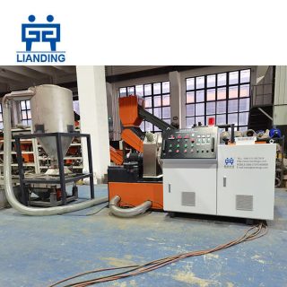
This is multifunctional small plastic pelletizing line. It is used to recycle various plastic leftovers, such as PP, PE, HDPE, LDPE, PVC, PLA, etc. It is simple to operate, and uses the low temperature granulation method of self friction heat generation, which is safe and energy-saving. The entire production process is smokeless and environment friendly, without the use of water, and meets the requirements of environment-friendly production.
Reviews
There are no reviews yet.